


MTBF and Lifespan: Key Parameters for Evaluating Product Reliability and Durability
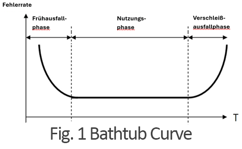
1. Early Failure Phase
The first phase is the early failure phase, which occurs at the beginning of a product’s lifespan. During this period, the product experiences a high failure rate, primarily due to manufacturing defects that may not have been detected during pre-shipment testing. At CINCON, every power supply undergoes 100% testing to ensure that each unit meets all specifications before shipment, effectively eliminating early failures.
2. Operational Phase
The second phase is the random or constant failure phase, also referred to as the normal failure rate of the design. This phase represents the period during which the product is in regular use. The failure rate during this period is expected to be low and stable, remaining nearly constant.
3. Wear-Out Failure Phase
As products remain in operation for an extended period, the failure rate begins to increase due to material degradation and wear. This process accelerates over time until all units eventually fail.
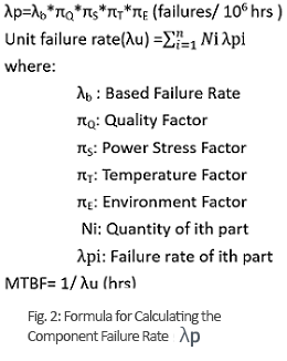
MTBF (Mean Time Between Failures)
MTBF and lifespan are critical parameters that must be considered during the product design phase. They help identify potential problem areas by pinpointing overstrained components or determining the biggest contributors to failure rates. These parameters are also key indicators for developers and engineers in selecting a reliable power supply.
Safety engineers frequently use various methods and standards to calculate a product’s MTBF value. Several reliability prediction standards exist, including MIL-HDBK-217F and Telcordia SR332 (Bellcore). These two are among the most widely used reliability standards in the market, particularly in military and telecommunications applications.
MIL-HDBK-217: A Widely Used Standard
MIL-HDBK-217 provides two calculation methods:
- Part Stress Analysis Prediction – Used in later design phases.
- Parts Count Reliability Prediction – Applied in early design stages and during initial product development.
- Ambient temperature
- Electrical stress
- Base failure rate
- Power rating
- Operating environment factor
- Component quality factor
Example Calculation
Consider a power module with an MTBF of 1000K hours (approximately 114 years). This does not mean that every module will operate for 114 years without failure.
Since MTBF = 1/λ, it follows that:
- λ = 1/MTBF = 1/114 years, meaning the average failure rate of this power module is approximately 0.88% per year.
- In other words, 8.8 units per 1000 will fail on average each year.
Lifespan
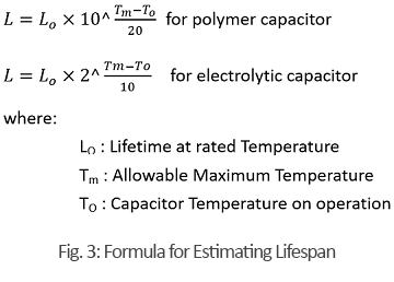
In the context of AC/DC power supplies, one of the most critical components is the internal aluminum electrolytic capacitor. However, this capacitor also has the shortest lifespan, which is why it is often referred to as a “critical component.” The expected lifespan of a power supply can be estimated by evaluating the expected lifespan of this capacitor.
The durability of a capacitor depends on several application-specific factors, with operating temperature being a key determinant. Temperature plays a major role in the aging of internal structures and the degradation of electrical properties over time.
- For electrolytic capacitors, the expected lifespan doubles when the component temperature is reduced by 10°C (Arrhenius equation).
- For polymer capacitors, a tenfold increase in lifespan can be achieved by reducing the component temperature by 20°C.
How Does MTBF Differ from Lifespan?
As outlined in the previous information, the main difference is that MTBF considers all components, while lifespan focuses specifically on electrolytic capacitors. Another key distinction is that different methods are used to calculate MTBF.
- MTBF (Mean Time Between Failures) is a statistical value that represents the average time between two consecutive failures of a system.
- Lifespan (also referred to as service life) defines the total operational time of a product until it permanently fails and can no longer be repaired.
Conclusion
In summary, MTBF and lifespan are two distinct but complementary parameters used to evaluate product reliability and durability:
- MTBF helps understand failure frequency during operational time and is particularly useful for maintenance and servicing planning.
- Lifespan provides insight into the total expected operational duration of a product, which is crucial for long-term planning and component replacement.